In modern robotics, achieving seamless human-robot interaction is essential for intuitive and effective operation. This project focuses on implementing impedance control for the Franka Emika Panda robotic arm to enhance compliance and ease of use during manual guidance. By designing an optimized virtual impedance model, the system regulates the dynamic interaction between the user and the robotic arm, enabling smooth and effortless dragging motions.
The primary objective is to fine-tune the impedance control framework to minimize user effort while maintaining stability and responsiveness. This involves carefully adjusting virtual mass, damping, and stiffness parameters to strike a balance between compliance and precision. Leveraging the Panda arm’s advanced control capabilities ensures high performance and adaptability.
This work establishes a solid foundation for future projects exploring advanced human-robot interaction techniques. By refining impedance control strategies, subsequent research can address more complex applications, such as adaptive assistance in dynamic environments, autonomous collaboration, and advanced manipulation tasks. These advancements will further enhance the intuitiveness and functionality of robotic systems.
This project was done by me and Courtney
Impedance control is a hybrid motion-force control strategy that governs the interaction between a robot and its environment. It is widely used to regulate the dynamic relationship between force and motion, ensuring a compliant and smooth interaction. The control law for impedance control is based on defining a desired mass-spring-damper system, as expressed by the task-space behavior:
Equation:
The parameters M, B, and K are tuned to achieve the desired dynamic behavior of the robotic system. For instance:
The impedance control strategy can also be analyzed using its frequency response characteristics. The impedance is defined as the transfer function between position perturbations and forces:
Here, Z(s) represents the system's impedance in the Laplace domain. The inverse of impedance, known as admittance, is given by:
A high impedance system (e.g., with large K and B) resists motion disturbances but responds minimally to external forces, whereas a low impedance system (e.g., with small M, B, and K) is more compliant and allows greater motion for a given force. For applications requiring user interaction, such as dragging a robotic arm, a compliant behavior is often desired to make the interaction smooth and effortless.
Impedance control can be implemented using feedback laws that map task-space positions or torques to forces. The parameters M, B, and K are chosen to achieve the desired behavior, ensuring stability and adaptability during interaction.
Me and Courtney implemented it based on libfranka librarywhich is a C++ library provided by Franka. We implemented three different modes and compare the perforce with the default one. We called them as damping mode, friction_compensation mode, and the default mode (white-light mode). Damping mode is adding an extra negative damper to help user feel weightless when moving the robot. Friction_compensation, is add constant joint impedance to compensate the influence of friction in each joints.
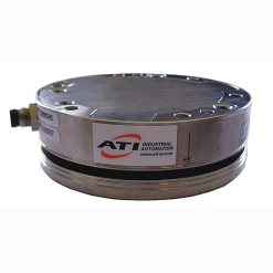
A force/torque sensor Axia80-M8 has been used to provide accurate reading about how much force and torque the user applied when using the impedance control mode to move the robot. Also 3D printed a customed handle which allows user drag the robot easier.


For data collection, we first need to modify the ip-address of the ft sensor, Franka, and station of Franka, to make sure they are able to communicate with each other. Then we used a Net F/T Sensor Driver to launch the controller and ros2 bag to record data. For robot data, it been saved as csv file when we drag it using impedance control. We also wrote a python pipeline for data processing and analyzing.
To find the best mode, We purpose a dynamic equation to describe the force that the user used: \( f(t) = m*a(t) - c * v(t) \) Then we collect data using each impedance control mode and move in x, y, z direction seperately and finally calculate m and c. We assume, the best mode should have a relative small m and c. and performance keep stable in all direction. We also plot the 3D-plot to show the relationship between acceleration, velocity and force. The conclusion is, damping mode is the best.
| Condition | Axis | m | c |
|---|---|---|---|
| Impedance Force | X | -1.42764592 | 1.0066388 |
| Y | 15.76363316 | 1.04373732 | |
| Z | 8.94264416 | 13.59926614 | |
| Damping | X | 0.09225413 | 2.62787636 |
| Y | 6.83681977 | -3.70447808 | |
| Z | 1.24047087 | 13.94127596 | |
| Friction Compensation | X | -3.21932284 | 1.68266821 |
| Y | 1.76315165 | 2.38112476 | |
| Z | 12.08837463 | 12.94580011 | |
| White Light | X | -8.55692881 | 3.82439509 |
| Y | 12.06393627 | 0.78625834 | |
| Z | 14.77014982 | 25.40289417 |