I graduated from Ohio State University in 2023 with a B.S. in Mechanical Engineering and a minor in Computer Science. Through various projects related to robotics during my undergrad, I gained knowledge and experience in path planning and controlling for a differential drive mobile robot. I also designed a robotic arm and applied deep learning algorithms. I am a Masters in Robotics student at Northwestern University. My main interests are in SLAM, machine learning, and computer vision.
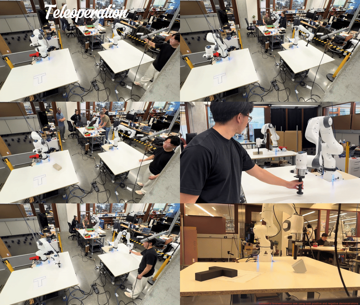
ResumeThe purpose of this project is to leverage ergodic imitation to learn both desirable and undesirable behaviors. To facilitate effective data collection, I first implemented an impedance control mode for a 7-DoF collaborative robotic arm (Franka) in collaboration with Courtney. Subsequently, I developed a haptic-guided teleoperation system for the Franka robot. This system enables the user to control Franka 1, which operates in impedance control mode, and couples its movements to Franka 2, such that any motion of Franka 1 is mirrored by Franka 2.
Following this, I employed a learning-from-demonstration (LfD) approach to derive robust task definitions from a combination of positive and negative demonstrations. The algorithmic framework for task learning is based on the ergodic metric, a measure of the information content in motion. Finally, I demonstrated the efficacy of this learning approach on (.......) using the 7-DoF Franka arm.
To achieve the goal of the project I wrote 4 functions.
Input: The input of the function includes config, speed, timestep, max_speed
config: A 12-vector representing the current configuration of the robot (3 variables for the chassis configuration, 5 variables for the arm configuration, and 4 variables for the wheel angles).
speed: A 9-vector of controls indicating the wheel speeds and the arm joint speeds
timestep: A timestep
max_speed: A positive real value indicating the maximum angular speed of the arm joints and the wheels.
For example, if this value is 12.3, the angular speed of the wheels and arm joints is limited to the range [-12.3 radians/s, 12.3 radians/s]. Any speed in the 9-vector of controls that is outside this range will be set to the nearest boundary of the range.
Output: The return of the function is new_config
new_config: A 12-vector representing the configuration of robot.
The function NextState is based on a simple first-order Euler step, i.e., new arm joint angles = (old arm joint angles) + (joint speeds) * new wheel angles = (old wheel angles) + (wheel speeds) * new chassis configuration is obtained from odometry.
Input: The input of the function includes Tse_initial, Tsc_initial, Tsc_goal, Tce_grasp, Tce_standoff, and k.
Tse_initial: The initial configuration of the end-effector in the reference trajectory
Tsc_initial: The cube's initial configuration
Tsc_goal: The cube's desired final configuration
Tce_grasp: The end-effector's configuration relative to the cube when it is grasping the cube
Tce_standoff: The end-effector's standoff configuration above the cube, before and after grasping, relative to the cube
k: The number of trajectory reference configurations per 0.01 seconds
Output: The Return of the function is N_final
A representation of the N configurations of the end-effector along the entire concatenated eight-segment reference trajectory. Each of these N reference points represents a transformation matrix T_se of the end-effector frame e relative to s at an instant in time, plus the gripper state (0 or 1).
Input: The input of the function includes X, Xd, Xd_next, Kp, Ki, delta_t
X: The current actual end-effector configuration (also written T_se).
Xd: The current end-effector reference configuration (i.e., T_se,d).
Xd_next: The end-effector reference configuration at the next timestep in the reference trajectory, (i.e., T_se,d,next, at a time Delta t later.
Ki, Kp: the PI gain matrices K_p and K_i.
delta_t: The timestep Delta t between reference trajectory configurations.
Output:
V: the commanded end-effector twist expressed in the end-effector frame
Xerr: the error twist.
The function is used to help the robot arm avoid singularities. I choose both joint 3 and joint 4 to be always less than -0.3.
Input: The input of the function includes joint_theta
joint_theta: the theta needed to be check whether reach the limits
Output:
res: which joint reaches the limits
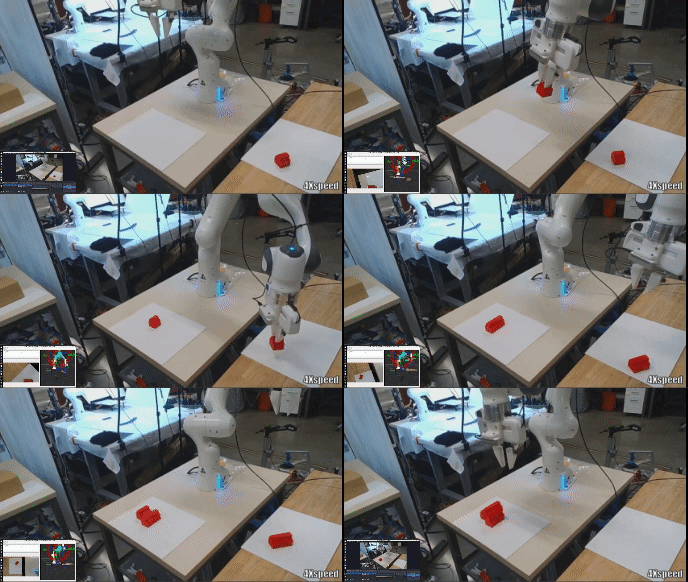
This project uses the Franka Emika Panda arm to solve a 3D bin packing problem which is an optimization challenge that involves efficiently packing a set of items of different sizes into a container, while minimizing wasted space and maximizing space utilization. It uses computer vision to detect the dimension and location of the object needed to be packed, and it uses Moveit2 to plan the trajectories.
Detecting the dimension of the object and finding the precise location of the project are the keys in this project. A realsense D435 is mounted on the robot. The object was detected and tracked using the RGB camera data and depth data provided by the Intel RealSense camera. All potential objects are a red color, and their location is determined using color masking in OpenCV to isolate the red pixels in the camera’s view. A contour was drawn around the red area, and the centroid of the contour and four more points on the edges were found. Then the grasp position and orientation of the object were found. The object will be placed on the “bin” and the robot will move to the observe position first. Once the camera detects an object appears, the robot will move to the top of the object to make sure the object is at the center of the camera to better detect the dimension of the object.

In order to finish grasping/placing process accurately and reliably every time, a custom gripper was designed, as well as the shape of the objects.
The grasping process include 3 steps
Move to the observe position
Move to the checking position (camera is on the top of the object)
Move to the actual position of the object and grasp it.
A custom wrapper interface was used in controlling the robot during both grasping and placing. The purpose of the wrapper interface was to make implantation easier; it offers a simpler way of planning trajectories. The wrapper was write in Making Pour Over Coffee with a Robot Arm project
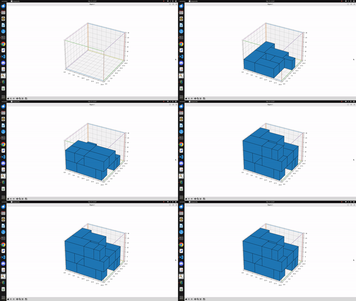
Here are some constraints in this project: 1. All objects are rectangular. 2. the high is the same. 3. The size of the container is 9cm*9cm*10cm. 4. the dimension of the incoming object is unknown, and the order is random. 5. The object can be placed wherever as long as it is in the bin. For this project, Best-fit algorithm was used to solve this 3D rectangular packing problem. Its input is a list of items of different sizes, the output the the location of the item to place. The best-fit algorithm uses the following heuristic:
It keeps a list of open bins, which is initially empty.
When an item arrives, it finds the bin with the maximum load into which the item can fit, if any. The load of a bin is defined as the sum of sizes of existing items in the bin before placing the new item.
Here is a gif shows how this algorithm works
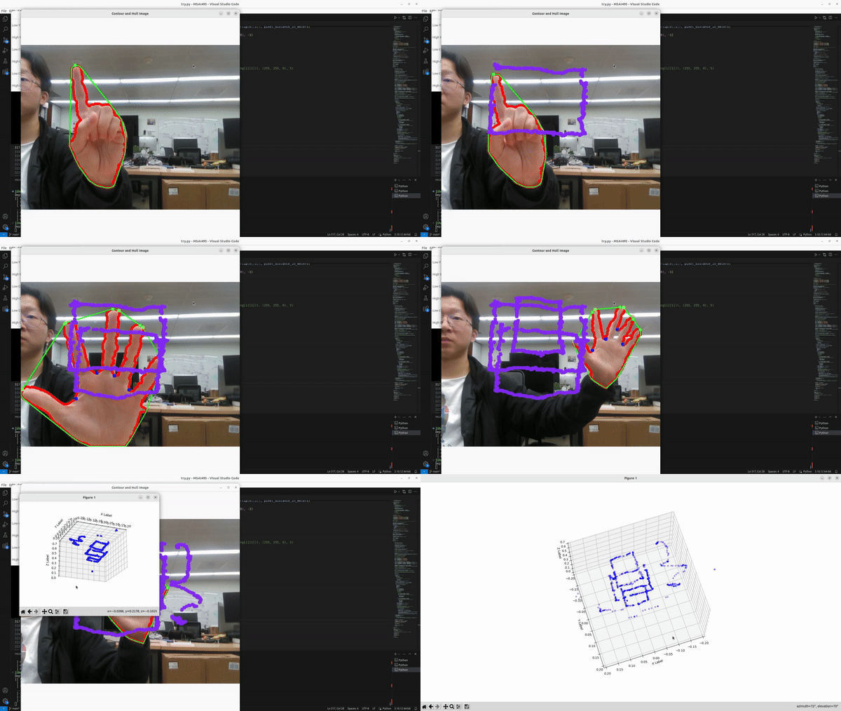
The purpose of the project is to track the location of fingertip in realtime and draw the path of fingertip movement in 3D.
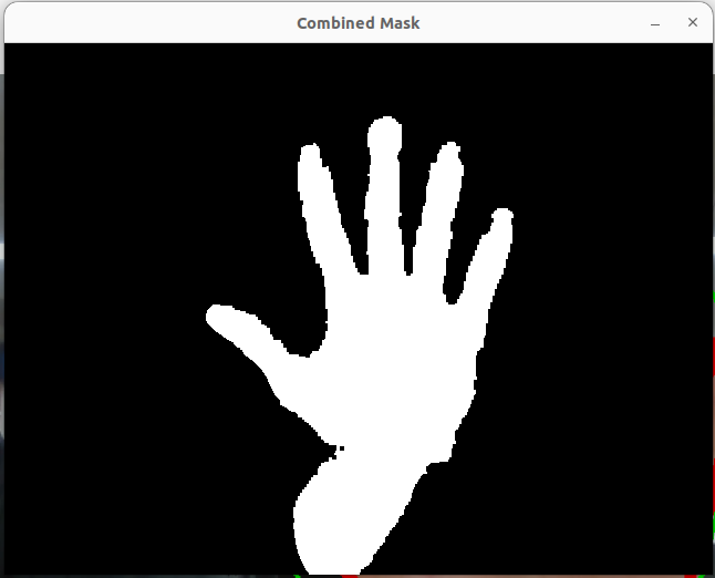
The first step is background subtraction and skin Color extraction. I decided to use YCrCb color ranges since many studies show that YCrCb color ranges are best for representing the skin color region. I first split it into 3 channels (Y, Cr, Cb) and threshold each channel independently. For each channel, I use morphology operators to remove noise and latter combine them using cv2.bitwise_and(mask_Y, cv2.bitwise_and(mask_Cr, mask_Cb)). Last, threshold binarization to smooth the image
The result image after Image Segmentation :
Computing a convex hull for an object and compute its convexity is a good way to find the shape of human hand as hand shapes are very well characterized by such defects. The convexity defects getting from openCV include information of start points, end points, depth points, and distance between the farthest contour point and the hull
The issue is these information include noise. To determine precise fingers locations, it must meet several criteria below:
i.Depth of each defects must be longer than palm center radius
ii. Angle between start point and end point must be less than 90°
To find the angle I implement the law of cosines
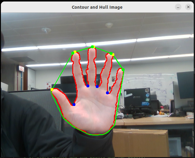
With all the information from the previous steps, I can find all finger locations when the user open palm. Next step, I want to perform gesture recognition based on simple and heuristic assumptions. Currently, I only focus on two gestures
i.Open Palm—4–5 fingers detected
ii.ready to draw—1 fingers detected
Dectect the first gesture is realtively easy as I meantioned before. However, the information from the previouse steps are not enough to find the fingertip when use only raise one finger. The way of detecting one finger can be explained by the following picture
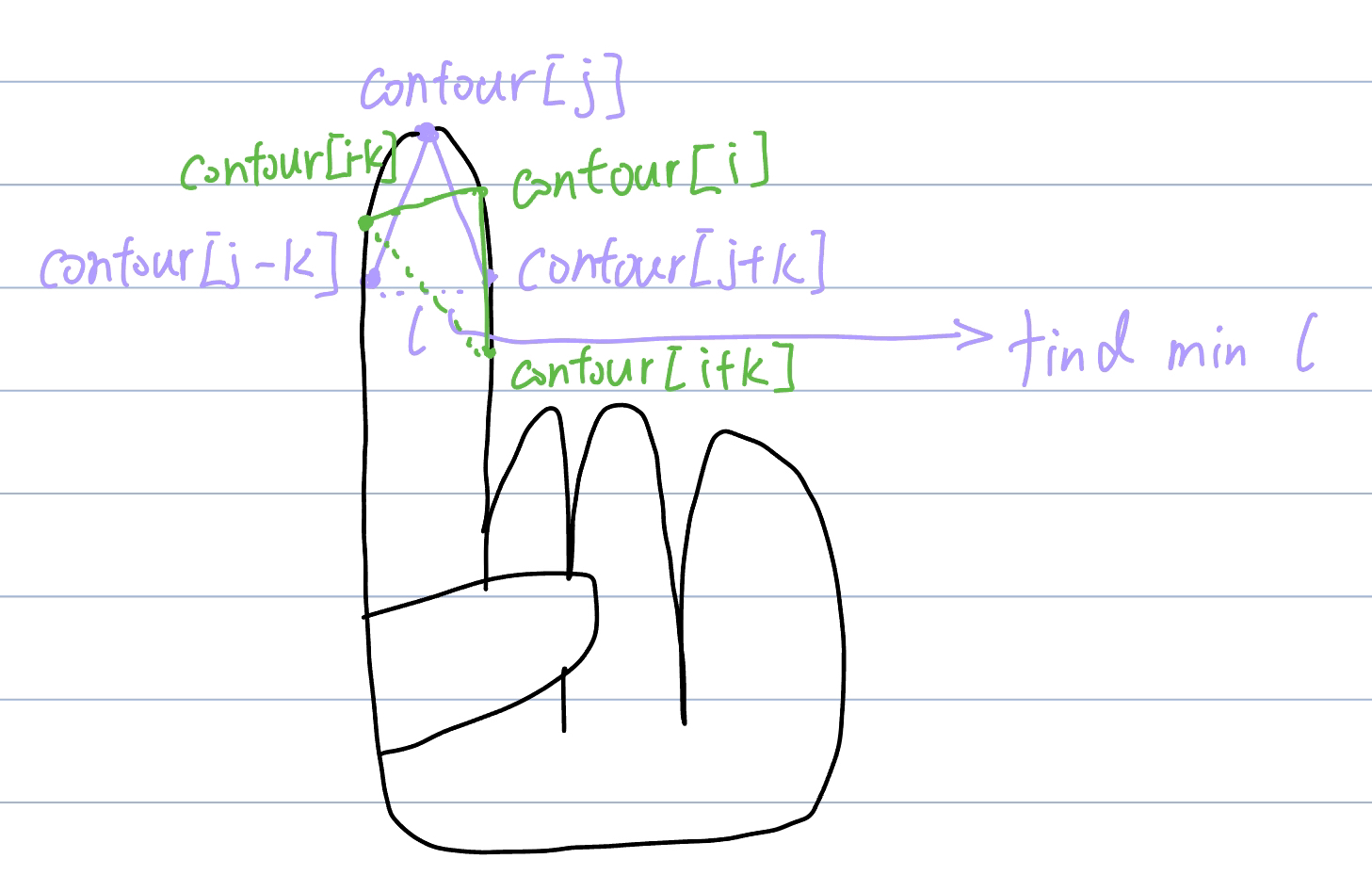
K is a constant value, for each potential finger location, I find a pair of points (contour[i-k] and contour[i+k]) and calculate the location between the pair of points. This distance been defined as l, the potential finger location with the samllest l will be consider as the precise finger location
It will start drawing only when user raise one finger. This allow user to open palm to stop drawing and change where they want to draw.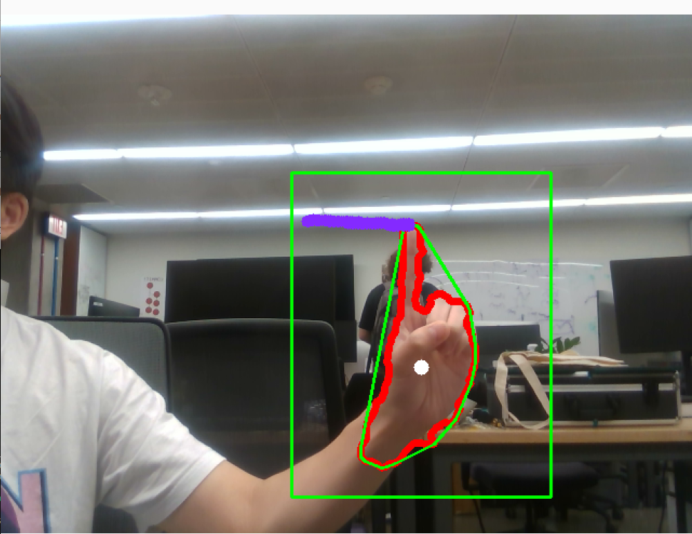
Also, since I am using realsense D435i which is a depth camera, I am able to record all 3D location of the path.
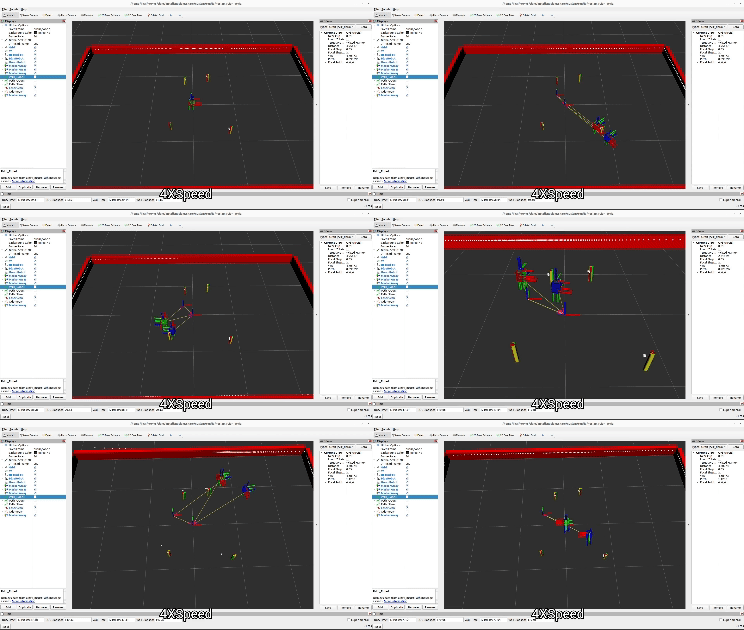
This project consists of several ROS packages
A library for handling transformations in SE(2) and other turtlebot-related math which include
geometry2d - Handles 2D geometry primitives.
se2d - Handles 2D rigid body transformations.
frame_main - Performs some rigid body computations based on user input.
diff_drive - Includes all functions related to the kinematics of wheeled mobile robots.
URDF files for Nuturtle turtlebot3_burger. Able to display multiple turtlebot3 models in rviz, each appearing with a different color. Also be able to change the physical properties of the robot by editing a yaml file.
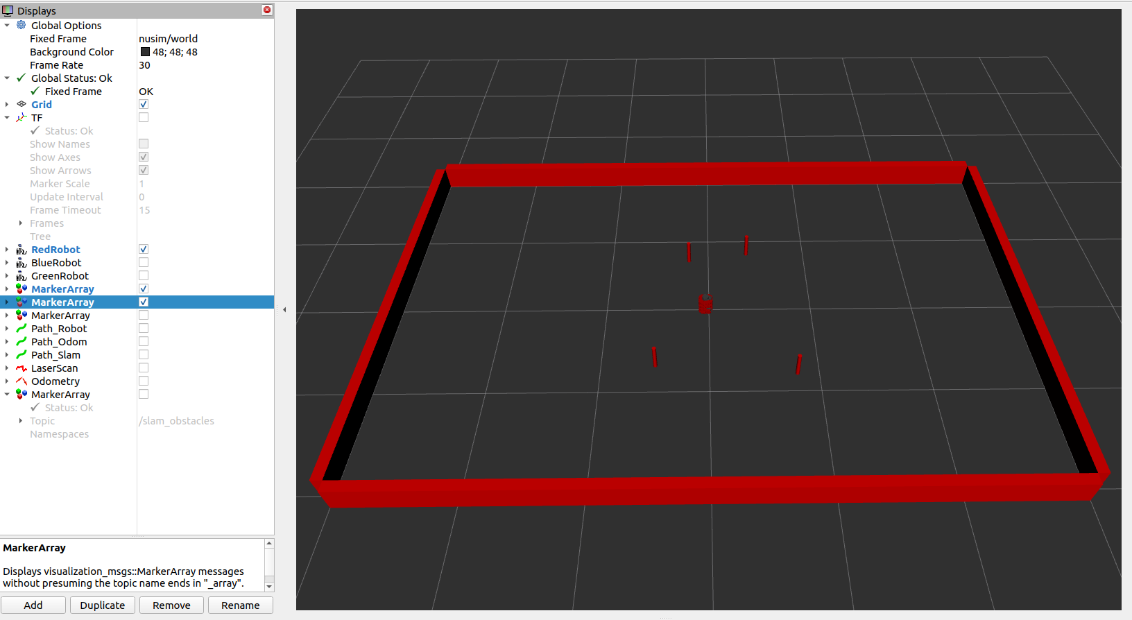
Create the basic environment for the robot. Allow the robot to move, according to simulated kinematics, but through the same publisher/subscriber interface that an actual turtlebot uses.
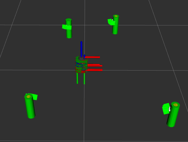
The primary component of this project is the implementation of feature-based extended Kalman filter simultaneous localization and mapping (EKF-SLAM). The EKF-SLAM algorithm consisted of three steps: initialization, prediction, and update. At each timestep, odometry and sensor measurements were used to estimate the state of the robot and landmarks. The prediction step updated the estimate of the full state vector and propagated uncertainty using the linearized state transition model. The update step involved computing the theoretical measurement given the current state estimate, the Kalman gain, the posterior state update, and the posterior covariance.
To detect cylindrical landmarks, the landmarks node reads LIDAR data and divides the data into clusters, and then performs supervised (circular regression) learning on each of the clusters to determine which of the clusters should be counted as landmarks.
The purpose of the project is to use the Franka Emika Panda arm to brew a cup of pour-over coffee. Computer vision and AprilTags were used to find the location of each object, and a custom wrapper package for MoveIt was written to control the robot. This project was done by a group of five in 3 weeks.
Group Members: Anuj Natraj, Carter DiOrio, Stephen Ferro, Kyle Wang
botrista Package:
camera_localizer: localizes the d435 and d405 cameras and publishes transforms for april tags seen by the cameras from the robot base
coffee_grounds: controls the actions for picking up and dumping the coffee scoop
cup_detection: handles detection of the coffee cup in the cup holder and triggers the rest of the routine. also publishes a transform to the top of the coffee cup
delay_node: handles the delay service which is used to pause the robot for a specified time at certain points in the routine
grasp_node: offers the grasp_process action, which is used to grap the "standard" handle used for the kettle, pot, and filter
handle_detector: tracks the blue and green tape on the handles of the objects using the d405 camera and publishes a tf for the object handle
kettle: handles action for picking up, pouring, and placing the kettle
pick_filter: offers the action to pick up the coffee filter
pot: handles action for picking up, pouring, and placing the coffee pot
pouring: offers the pour action, which is used by the kettle to create spiral motions
run_botrista: the main node which offers the make_coffee action
botrista Package:
grasp_planner: handles planning and execution of grasp actions
moveitapi: a wrapper class for sending moveit commands to a robot like the Franka
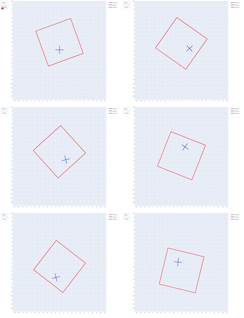
The goal of this project is to simulate a jack bouncing inside of a moving box. The drawing below shows the configuration and transformation of frames I used. For simulation, I simulate the jack starting at the center of the box with zero initial velocity and zero theta for 10 seconds with a time step of 0.01s.
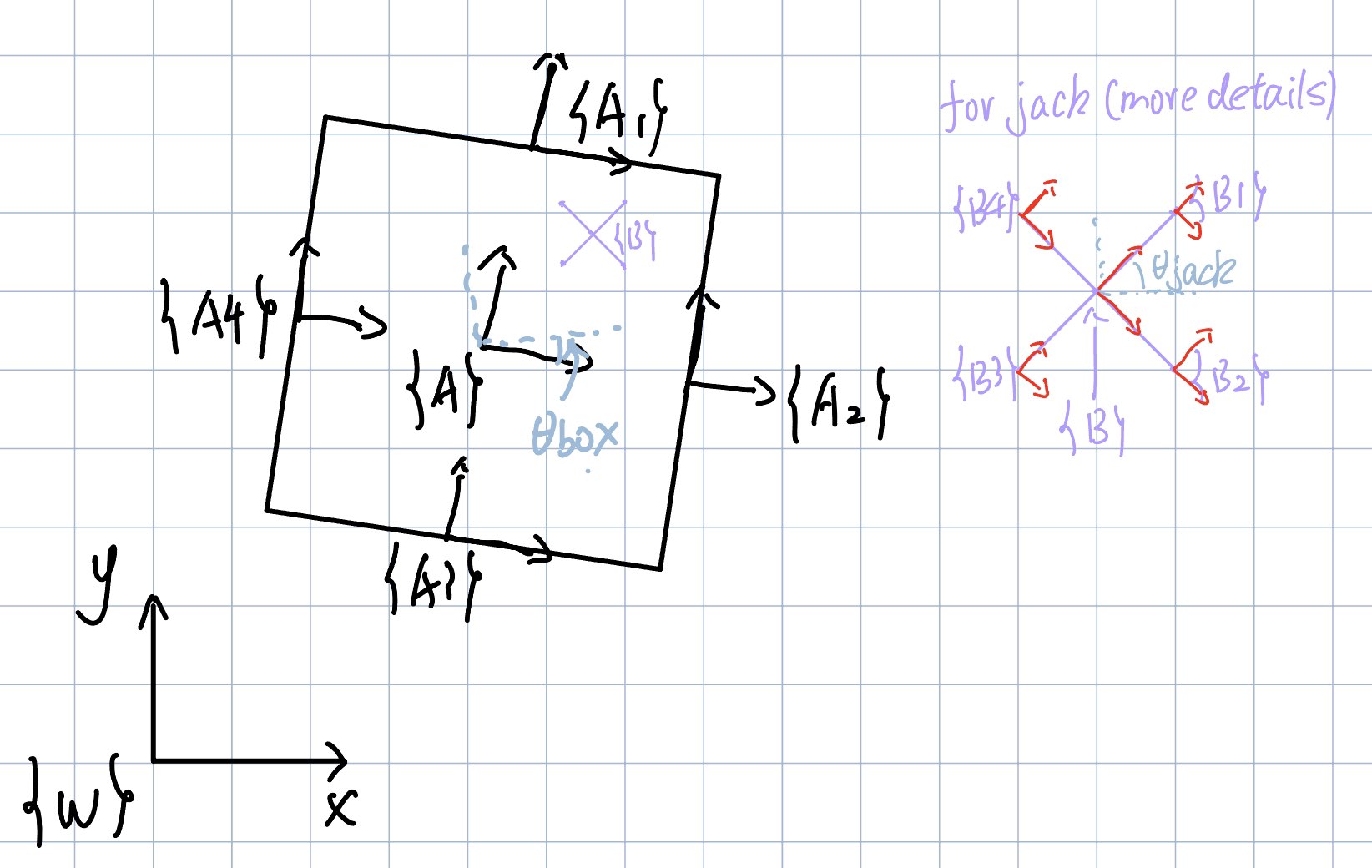
Frame W is the world frame, frame A is the frame of the center of box, frame B is the frame of the center of the jack. g_B1, g_B2, g_B3, g_B4 are the transformations from frame B to the four edges of the jack.
Lagrangian equation of the system : L = KE - V. For kinetic energy, first get the body velocity of the box by calculating their rigid body transformation to world frame. Next convert this 4 by 4 matrix to a 6 by 1 vector and last calculate KE. (I assume the center of the mass is the center of the geometry). Last, use the same method for the jack.
$$\ KE = \frac{1}{2}⋅ω^T⋅I⋅ω$$For potential energy, get the y value of the box relative to world frame and use the same method for the jack
$$\ V=mgh$$Euler-Lagrange:
$$\ \frac{∂}{∂t}\frac{∂L}{∂\dot{q}}−\frac{∂L}{∂q}=F$$The constrains:There are a total of 16 constraints for this system. They are each edge of the jack reach the four sides of the box.
The external force:I tried different magnitudes of force, and I found the two blow works best for me.
$$\ F_y = m_{box} * g *1.012$$ $$\ F_theta = m_{box} * g * 0.5$$The impact update law:
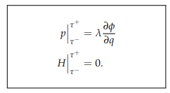
The impact happened when one edge of the jack collided with one side of the box. P is the momentum; H is the Hamiltonian of the system. After defining the 16 constrains of the system, evaluate the related expressions at $\ τ^+$ and $\ τ^-$ and solve them for $\ \dot{q}(τ+)$, and the results will be the impact update rules. With the symbolic solutions for impact update, we can numerically evaluate them and define a function for the impact update in the simulation loop.
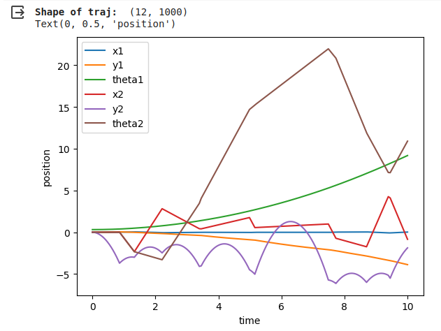
When the simulation begins, the jack falls because of gravity. Since I give a force in the positive y direction and a rotation force to the box, the box will not fall, and the box will start rotating slowly. When the jack hits the sides of the box, it will bounce back, and the direction depends on the angle of the sides it collides. The simulation looks reasonable to me, the jack will bounce back, and the direction is related to the angle of the sides it collides. Also, since I chose the box mass to be way heavier than the jack, the collision will not affect the performance of the box. The blow picture shows the change of 6 related to time. It can further prove mt work is reasonable, from y2, we can clearly see where collision happened. Theta2 first increasing and then decreasing is also due to the collision.
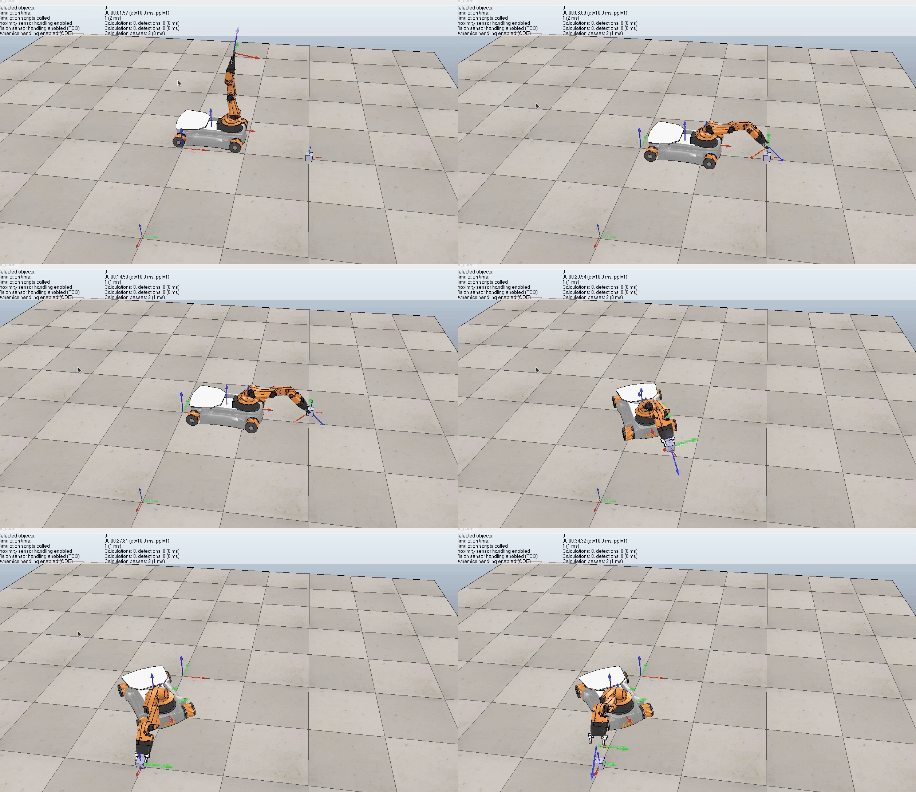
The propose of this project is writing software that plans a trajectory for the end-effector of the youBot mobile manipulator (a mobile base with four mecanum wheels and a 5R robot arm), performs odometry as the chassis moves, and performs feedback control to drive the youBot to pick up a block at a specified location, carry it to a desired location, and put it down.
To achieve the goal of the project I wrote 4 functions.
Input: The input of the function includes config, speed, timestep, max_speed
config: A 12-vector representing the current configuration of the robot (3 variables for the chassis configuration, 5 variables for the arm configuration, and 4 variables for the wheel angles).
speed: A 9-vector of controls indicating the wheel speeds and the arm joint speeds
timestep: A timestep
max_speed: A positive real value indicating the maximum angular speed of the arm joints and the wheels.
For example, if this value is 12.3, the angular speed of the wheels and arm joints is limited to the range [-12.3 radians/s, 12.3 radians/s]. Any speed in the 9-vector of controls that is outside this range will be set to the nearest boundary of the range.
Output: The return of the function is new_config
new_config: A 12-vector representing the configuration of robot.
The function NextState is based on a simple first-order Euler step, i.e., new arm joint angles = (old arm joint angles) + (joint speeds) * new wheel angles = (old wheel angles) + (wheel speeds) * new chassis configuration is obtained from odometry.
Input: The input of the function includes Tse_initial, Tsc_initial, Tsc_goal, Tce_grasp, Tce_standoff, and k.
Tse_initial: The initial configuration of the end-effector in the reference trajectory
Tsc_initial: The cube's initial configuration
Tsc_goal: The cube's desired final configuration
Tce_grasp: The end-effector's configuration relative to the cube when it is grasping the cube
Tce_standoff: The end-effector's standoff configuration above the cube, before and after grasping, relative to the cube
k: The number of trajectory reference configurations per 0.01 seconds
Output: The Return of the function is N_final
A representation of the N configurations of the end-effector along the entire concatenated eight-segment reference trajectory. Each of these N reference points represents a transformation matrix T_se of the end-effector frame e relative to s at an instant in time, plus the gripper state (0 or 1).
Input: The input of the function includes X, Xd, Xd_next, Kp, Ki, delta_t
X: The current actual end-effector configuration (also written T_se).
Xd: The current end-effector reference configuration (i.e., T_se,d).
Xd_next: The end-effector reference configuration at the next timestep in the reference trajectory, (i.e., T_se,d,next, at a time Delta t later.
Ki, Kp: the PI gain matrices K_p and K_i.
delta_t: The timestep Delta t between reference trajectory configurations.
Output:
V: the commanded end-effector twist expressed in the end-effector frame
Xerr: the error twist.
The function is used to help the robot arm avoid singularities. I choose both joint 3 and joint 4 to be always less than -0.3.
Input: The input of the function includes joint_theta
joint_theta: the theta needed to be check whether reach the limits
Output:
res: which joint reaches the limits
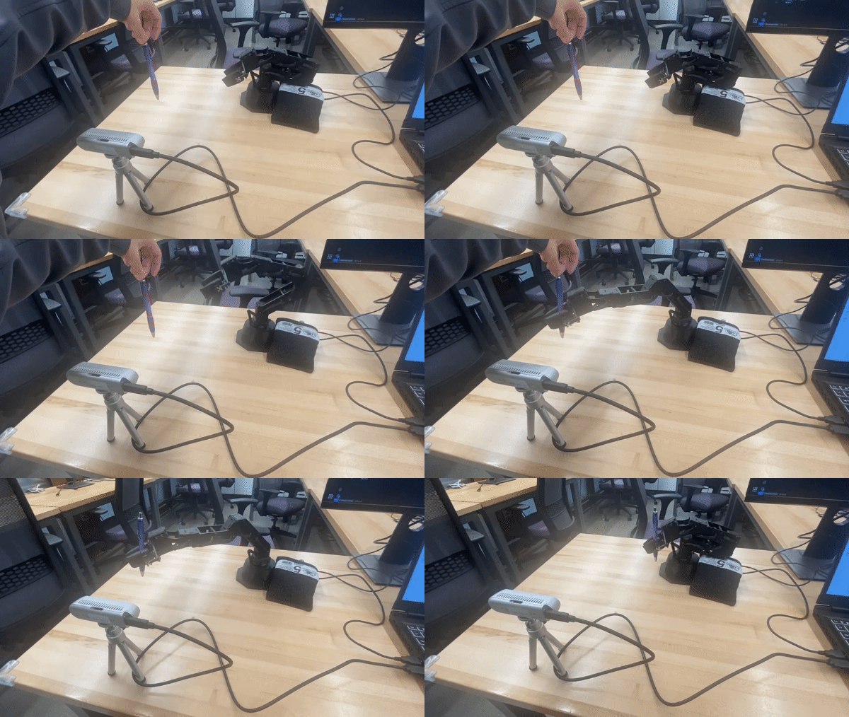
Use the RealSense to measure the 3D location of my purple pen. I use the interbotix_xs_toolbox to control the robot. Last get the robot capturing the pen.
The physical setup for this project requires the Trossen PincherX 100 and the Intel Realsense D435i. The field of view of the RealSense should substantially overlap with part of the PincherX's workspace and I decided to offset the D435i 90 degrees from the front of the PincherX.
The approach is to use classical computer vision techniques on the RGB image to locate the pen in 2D space. Then align the Depth map to the RGB image and use the pen location as a mask to get the 3D information. Finally, draw the contour of the pen and find the centroid of the pen. This information will be fed into a controller that will enable the robot to grab the pen.
I will use the interbotix_xs_toolbox to control the robot.
There are total four steps.
Measure The Pen Location.
Move forward until the pen is inside the grippers.
Close the gripper
Return to home position
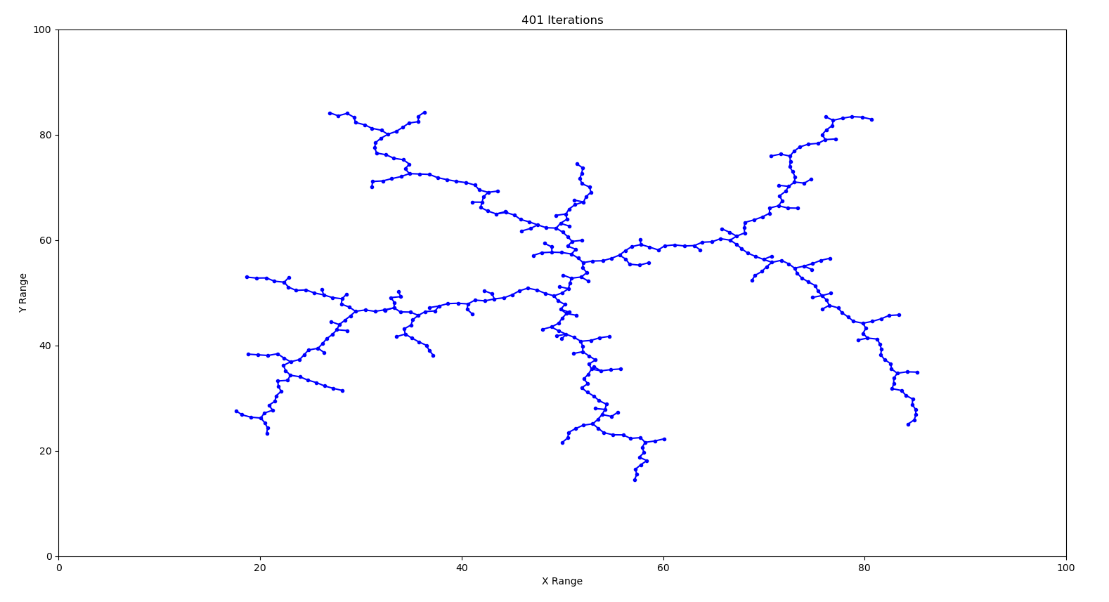
A Rapidly-Exploring Random Tree (RRT) is a fundamental path planning algorithm in robotics. Path planning is the task of moving a robot from one location to another, while avoiding obstacles and satisfying constraints. An RRT consists of a set of vertices, which represent configurations in some domain D and edges, which connect two vertices. The algorithm randomly builds a tree in such a way that, as the number of vertices n increases to ∞, the vertices are uniformly distributed across the domain D⊂Rn.
Implement an RRT in a two-dimensional domain, D=[0,100]×[0,100]. Use an initial configuration of qinit=(50,50) and Δ=1. Plot the result for a few different values of K
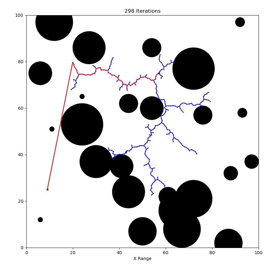
Compare to task 1 there are three modifications to make:Created 35 circle obstacles with random radius and random position to the domain. Collision Checking. Once find a path from a node in the tree to the goal state, I can traverse the tree backwards to the starting location to find the path
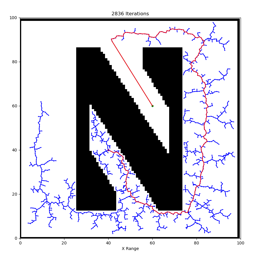
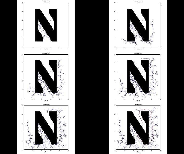
Now let's consider arbitrary objects, represented by black pixels in a binary image. I will load a binary image into script, and randomly choose starting and goal locations, and then plan a path.
